Since winter of 2020 I’ve been experimenting with switching DC/DC converters. The plan was to create an adjustable power supply for anode voltages in tube projects, that is cost efficient and doesn’t use exotic or rare parts – as well as gaining a more detailed understanding switching DC/DC converters.
I wanted to start small and not work with mains voltage-levels on the primary side right away. Instead the first goal should be stepping up 24V to 200-300V DC. A 300W/24V LED-lamp PSU brick proved ideal as power source.
Boost-converter
The simplest topology for stepping up DC is the boost converter. The input voltage is put across an inductor which draws current from the input to build a magnetic flux. Interrupting the current flow into the inductor causes the magnetic field to collapse, creating a high negative voltage pulse across the inductor. The high negative voltage is harvested using a single diode rectifier. This cycle is repeated thousands of times a second, making the circuit continuously pump energy from the input to the output side. The amount of energy pumped through can be throttled by reducing the time in which the input voltage is put across the inductor, therefore reducing the amount of flux buildup in it.
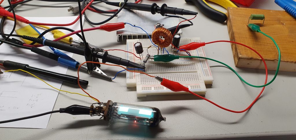
Flyback-converter
The boost-converter turned out unsuitable for covering a large voltage gap (24 to 300V) and simultaneous passing large currents through. This is because in order to keep the current up, the circuit has to pour so much flux into the inductor, the voltage peaks when collapsing the field would go beyond 500V, both exceeding the UDS rating of the switching MOSFET, as well as discharges into the air wasting power.
The solution comes in form of the flyback-converter. It works in the same way as the boost-converter, except that a second coil is added that is magnetically coupled to the switched inductor. The diode rectifier for harvesting pulses of the magnetic flux collapsing is moved to the second coil, which may in turn have many more windings. The voltage induced in the second coil is a multiple of that in the first one, depending on the two coils’ winding ratio.
Additionally, the flyback topology provides galvanic separation between input and output terminals.
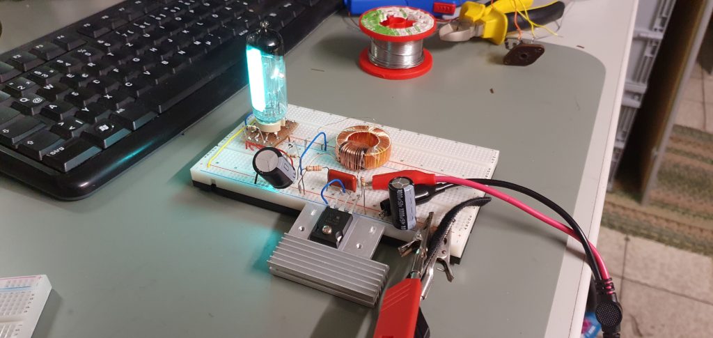
I decided to wind a coupled inductor myself for first tests, using a toroid core with a winding ratio of around 5, secondary to primary. The performance wasn’t too great. Creating a quality inductor with minimal parasitic resistance and capacitance is more difficult than it may seem!
Much improvement could be achieved by using a proper coupled inductor from a 24V switching PSU board. In my application, it’s used in reverse as it’s stepping voltage up instead of down.
This coupled inductor has several separate windings on it’s primary and secondary side, allowing to be connected in parallel or in series. After trying different combinations, the converter worked at around 72% efficiency.
I decided to use the TL494 PWM-controller chip to drive the converter. The TL494 has everything that’s needed: A stabilized voltage reference, multiple “error amplifier” opamps, a slow-start feature and open-collector/emitter output drivers. TL494 can be commonly found in PC PSUs. Half of the old PC PSUs I had lying around had this chip in them.
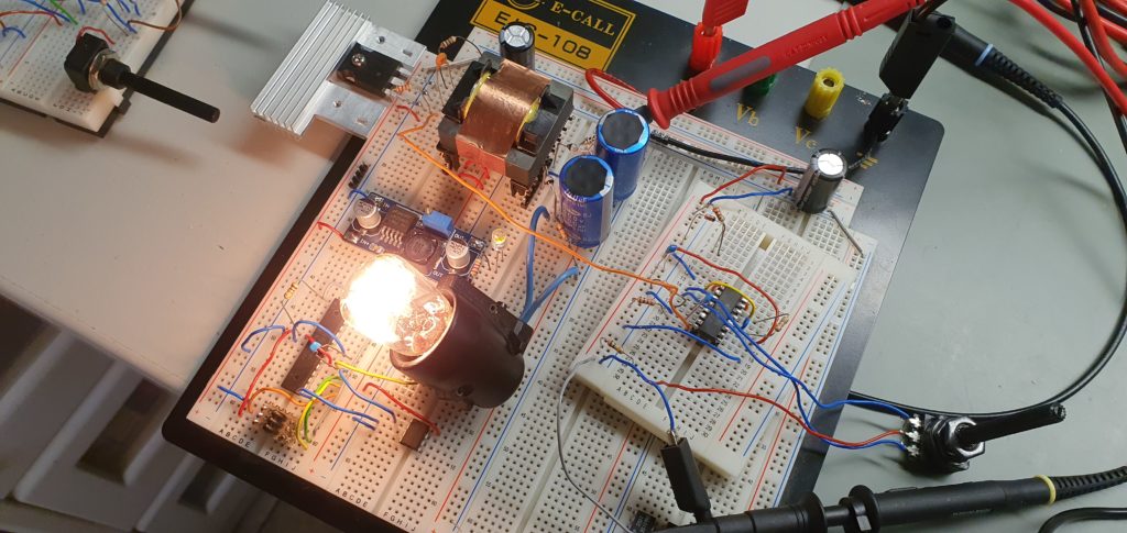
Another big issue was filtering the switching noise that backs the output DC. A CLC filter with electrolytic and ceramic capacitors was used. Afterwards the finished prototype was assembled on double sided perfboard.
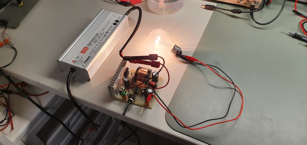
Finally, the 24V PSU, the HV converter board and a cheap V/A meter was put together neatly in an enclosure.
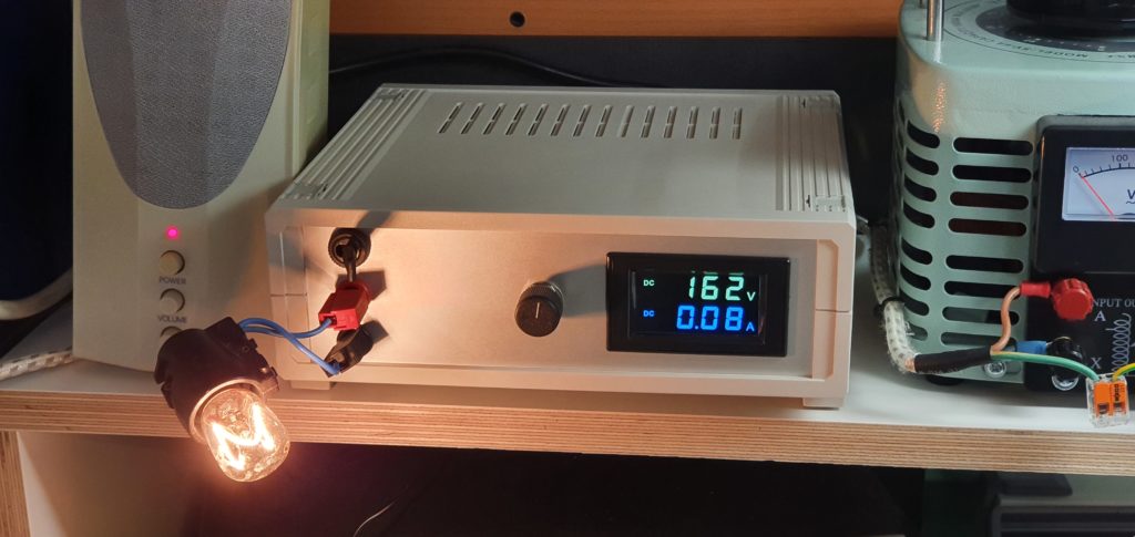
(more details will be added)

